
Staying in time - Data acquisition and transmission with R-Series V SSI (part 1)
The R-Series V is available with SSI output, among others. With the sensor, the user can choose between one asychronous and three synchronous modes for acquiring and transmitting the measurement data to the controller. Before the different modes are explained, it is first necessary to clarify:
What is SSI?
SSI is the abbreviation for Synchronous Serial Interface. This digital interface was introduced in 1985 by Max Stegmann GmbH (in 2002 Sick AG took over Max Stegmann GmbH) and is widely used for the transmission of absolute measured values in industrial environments. Among other things, this is due to the robustness as well as the quite simple structure of the interface. Thus, in a sensor like the R-Series V SSI for the transmission of data to the controller a shift register and a monoflop, also called “one shot”, are required. The monoflop is used to control the shift register.
As the name SSI implies, this interface transmits data serially, bit by bit. The data transmission can also be synchronized to a clock pulse specified by the controller.
How does SSI work?
With SSI, the data is transmitted serially, whereby the controller specifies the time of the polling. During data transmission, the procedure described below is carried out (Fig. 1):
- In the idle state, when no data is transmitted, the data line and the clock line are at the high level (1).
- The current position data is frozen in the shift register with the first falling clock edge. It is no longer possible to update the position data in this cycle (2).
- The bit is applied at the following rising edge (3).
- With the following falling edge, the transmission of the data begins with the Most Significant Bit (MSB) (4).
- This is repeated for each next lower bit until the Last Significant Bit (LSB) is transmitted.
- The standard one shot starts after the last falling clock edge (5). After the transmission of the LSB, the data line remains on the low level and the clock line on the high level until the end of the standard one shot. Then the sensor is ready for the transmission of a new data (6).
![]() Fig.1: Timing diagram of an SSI data transmission with a data length of n bits.
Fig.1: Timing diagram of an SSI data transmission with a data length of n bits.
With the R-Series V SSI, the current temperature inside the sensor electronics housing can be transmitted in addition to the position. According to the transmission diagram in Fig. 2, these data are transmitted one after the other due to the serial transmission method. First 8 bit for the temperature data and then 24 bit for the position data are transmitted, so that the total data length is 32 bit. If an alarm bit and a parity bit are transmitted in addition to the position data, these two bit are transmitted after the transfer of the 24 bit for the position data.
![]() Fig. 2: Structure of the SSI transmission telegram for the R-Series V SSI with different data length with alarm bit (A bit) and parity bit (P bit).
Fig. 2: Structure of the SSI transmission telegram for the R-Series V SSI with different data length with alarm bit (A bit) and parity bit (P bit).
Asynchronous data transmission with the R-Series V SSI
In asynchronous mode, the position data within the sensor is updated as fast as the sensor's measurement cycle allows, regardless of the controller. The controller only determines when the currently provided data is requested via the SSI interface. As shown in Fig. 3, the sensor performs measurements more frequently than the controller queries. In asynchronous mode, the time delay between starting the measurement and transmitting the position data, also called as dead time, varies.
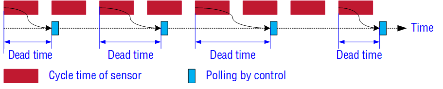
Fig. 3: Schematic representation of asynchronous mode for R-Series V SSI.
Synchronous data transmission with the R-Series V SSI
In the synchronous mode, the sensor adapts the execution of the measurement as well as the transmission of the position value to the data polling cycle of the controller. This means that the sensor synchronizes to the polling cycle and determines when the position values are requested by the control. Three variants of synchronous data acquisition and transmission are available with the R-Series V SSI:
- Synchronous mode 1
- Synchronous mode 2
- Synchronous mode 3
What is the synchronous mode 1 on the R-Series V SSI?
In synchronous mode 1, the sensor adapts to the clock of the controller and then starts its measurement so that it is completed just in time before the next query from the controller. The freshest measured value possible is transmitted (Fig. 4).
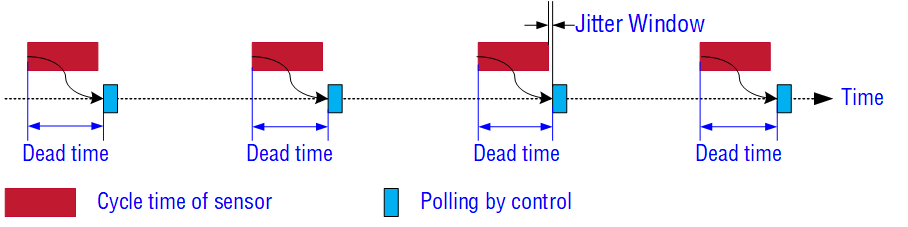
Fig. 4: Schematic representation of synchronous mode 1 for R-Series V SSI.
As can be seen in Fig. 4, the time delay between the start of the measurement and the transmission of the position value is constant. With an asynchronous measurement, the dead time varies over a wide range. A constant dead time allows an exact assignment of the measurement to a point in time and is an essential requirement for motion control applications. The dead time is minimized in synchronous mode (Fig. 5).
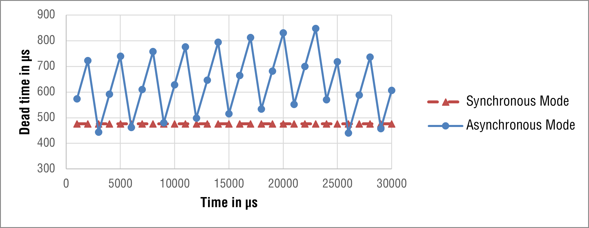
Fig. 5: Dead time in asynchronous and synchronous mode in the course of time.
What is the parameter "Jitter Window"?
It can happen that the given polling cycle of the control varies. This inaccuracy of the polling cycle is called timing jitter. If this occurs, the sensor cannot synchronize to the controller’s polling cycle in synchronous mode and displays the error "Sync Status Error" via the LEDs. One solution is to adjust the parameter Jitter Window. This parameter can be set on R-Series V SSI using the TempoLink smart assistant. The jitter window is the time between the end of the measurement and the next data request by the controller. This time is given in μs. The jitter window is shown in Fig. 4 for one polling cycle. The larger the jitter window, the sooner the sensor starts the next position measurement in order to be able to provide the current position value in time before the next polling cycle. If the data request by the controller is received earlier than expected due to an inaccurate polling cycle, the position measurement is already completed with a sufficiently large jitter window. However, increasing this parameter will increase the cycle time of the sensor. Therefore, the value of the jitter window has to be chosen carefully in order to select a proper ratio between the timing jitter of the polling cycle and the cycle time of the sensor.
To be continued in Part 2 where synchronous mode 2 and synchronous modus 3 of the R-Series V SSI will be explained.
GET IN TOUCH WITH US
You have a question about one of our products or would like more details on a possible application?
Click here to fill in our request form
Don't want to miss out on the latest blog updates and other news?
Click here to subscribe to our newsletter
Total customer satisfaction
We live by the promise of unparalleled service that
enables us to take all available means to exceed your expectations.
Click here to find out how we support our customers